Summary
cl-vectors is a pure Common Lisp library to create, transform and render anti-aliased vectorial paths.
It can be installed using ASDF-Install. See the documentation for details.
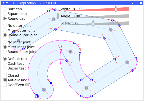
Example of application using cl-vectors and clx:
News
February 2013: The project is now released under the MIT license. The version was bumped to 0.1.5.
September 2010: I've updated the git repository to include pending changes (from 3 years ago..) and updated the source archive (version 0.1.4b).
December 2009: I've not worked on this project since 2007, but rest assured that this page will not disappear. You can still contact me (see below) about this project.
Projects using cl-vectors
- Vecto, by Zach Beane, is a high level interface to cl-vectors and also provides many interesting features to produce various vectorial drawing.
- McCLIM use it as an optional extension to render antialiased fonts purely in Common Lisp.
Downloads
Latest version: cl-vectors-0.1.5.tar.gz.
GIT repository: git://github.com/fjolliton/cl-vectors.git (browse)
Documentation
Changelogs
See here.
Contacts
The main author is Frederic Jolliton and can be contacted by email at frederic@jolliton.com.